
- Details
- Category: Blog
- Hits: 10683
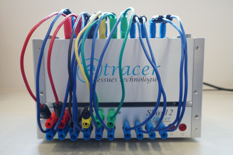
Introducing the Sbox12 automatic wiring box for etracer. The Sbox12 is designed to sit underneath the etracer Model-01 chassis and performs automatic wiring for the users.
Read more: Annoucing the Sbox12- An automatic wiring box for etracer
- Details
- Category: Blog
- Hits: 16169
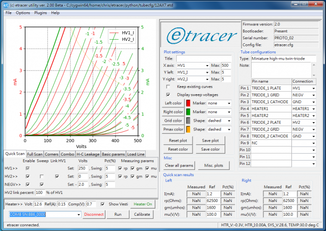
The etracer software version 2.xx GUI
Introduction
The GUI (Graphics User Interface) in the etracer software is simple yet effective. The seven tabs below the curves plot area controls the operating mode of the software.
There are three tabs provide three basic modes of measurements: [Quick Scan], [Full Scan] and [Corners]. [Quick-Scan] is designed to perform a quick measurement around a quiescent operating point. This test is similar to the test performed by a tradition tube tester such as Hickok TV-7 with more parameters generated. The [Full Scan] test scans the plate-volt vs. plate-current curves at different grid bias and plot the result. The [Corners] test tests the DUT under extreme voltage conditions.
The [Combo] tab allows the user to compose a combination of three basic test modes and it has the ability to detect an insertion or a removal of a DUT. This mode is useful for testing a tube lot of the same type.
The [H-C Leakage] tab allows user to test the leakage current between the heater and the cathode of a vacuum tube.
The [Basic Params] and the [Load Line] tab allows users to perform real-time analysis of the full-scan data.
Read more: Introduction to the PC control software version 2.xx
- Details
- Category: Blog
- Hits: 16422
I am not sure since when vacuum tube testers like etracer are categorized as "pulse-type" tube testers. And this type of tube testers are usually being criticized as not accurate because the DUTs are not biased at the quiescent point and hence during testing the temperature of the DUT is lower than the temperature of the DUT in the real circuits. However, little information can be found on the accuracy requirement. How bad is it? And how much deviation is acceptable? 1%? 10%. In this article I will explore this issue a little deeper and measurement data are provided for references.
Read more: The impact of working temperature to "pulse-type" vacuum tube testers
- Details
- Category: Blog
- Hits: 16582
In the Facebook etracer group a member asked how important it is to supply a test voltage beyond 400V. Why can't we just test a tube up to 400V and extrapolate the curves from there. Well, besides the trivial answer that extrapolation is not reliable there are actually situations where extrapolation simply doesn't work.
- Details
- Category: Blog
- Hits: 20124
As I mentioned in one of my earlier article the initial goal of etracer was an enhanced utracer. The project turned out to be a totally different design and shares nothing in common except the idea of using a capacitor to supply high voltages. the letter 'e' in etracer thus has multiple meanings. It can be enhanced, electron or essues. The key differences between etracer and utracer are listed below:
| etracer | utracer | |
| High voltage supply range | 0~750V | 0~400V |
| Negative supply range | 0~-180V | 0~-40V |
| Heater supply | 1.5V~27V regulated DC supply with a current capacity of at least 3A. One side of the heater supply is always connected to the system ground by a 0.1ohms current sensing resistor. | Heater voltage is emulated by chopping the 19V DC input. Or an external DC supply is required. |
| High voltage supply topology | Output voltage is 0~750Vdc referred to the system ground. | Output voltage is 19V above the system ground. When making a measurement the heater needs to be disconnected from the system. |
| Voltage charging time | Sophisticated DSP algorithms ensuring accuracy in the low-voltage range and fast charging time in the high voltage region | Fixed charging period. Charging time is significantly longer in the high voltage range (>200V) |
| ADC resolution and sampling rate | 14 bits/ 900k samples/sec | 10 bits |
Beside the technical differences etracer is offered as a built PCB while utracer is in un-built kit format. etracer also have a companion chassis, the Model-01 to save the users' precious time and possible frustration.
Page 2 of 3
- You are here:
-
Home

- Blog
