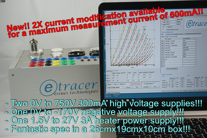
As I mentioned in one of my earlier article the initial goal of etracer was an enhanced utracer. The project turned out to be a totally different design and shares nothing in common except the idea of using a capacitor to supply high voltages. the letter 'e' in etracer thus has multiple meanings. It can be enhanced, electron or essues. The key differences between etracer and utracer are listed below:
| etracer | utracer | |
| High voltage supply range | 0~750V | 0~400V |
| Negative supply range | 0~-180V | 0~-40V |
| Heater supply | 1.5V~27V regulated DC supply with a current capacity of at least 3A. One side of the heater supply is always connected to the system ground by a 0.1ohms current sensing resistor. | Heater voltage is emulated by chopping the 19V DC input. Or an external DC supply is required. |
| High voltage supply topology | Output voltage is 0~750Vdc referred to the system ground. | Output voltage is 19V above the system ground. When making a measurement the heater needs to be disconnected from the system. |
| Voltage charging time | Sophisticated DSP algorithms ensuring accuracy in the low-voltage range and fast charging time in the high voltage region | Fixed charging period. Charging time is significantly longer in the high voltage range (>200V) |
| ADC resolution and sampling rate | 14 bits/ 900k samples/sec | 10 bits |
Beside the technical differences etracer is offered as a built PCB while utracer is in un-built kit format. etracer also have a companion chassis, the Model-01 to save the users' precious time and possible frustration.


