
Introduction
The maximum current measurement capability of etracer is designed to be 300mA. This capability is more than adequate for testing and tracing most of common audio tubes such as 300B, KT88 and 6550. However, it might be desired to have a higher current measurement capability for testing tubes like 6C33C or KT150. This application note describes the modification method needed to increase the current measurement capability to 600mA. Below figure shows a traced curves set with a Telefunken EL156 with a screen voltage of 500V!! under pentode connection. Please note the maximum plate dissipation is set to 100W to allow traces in the high current region.
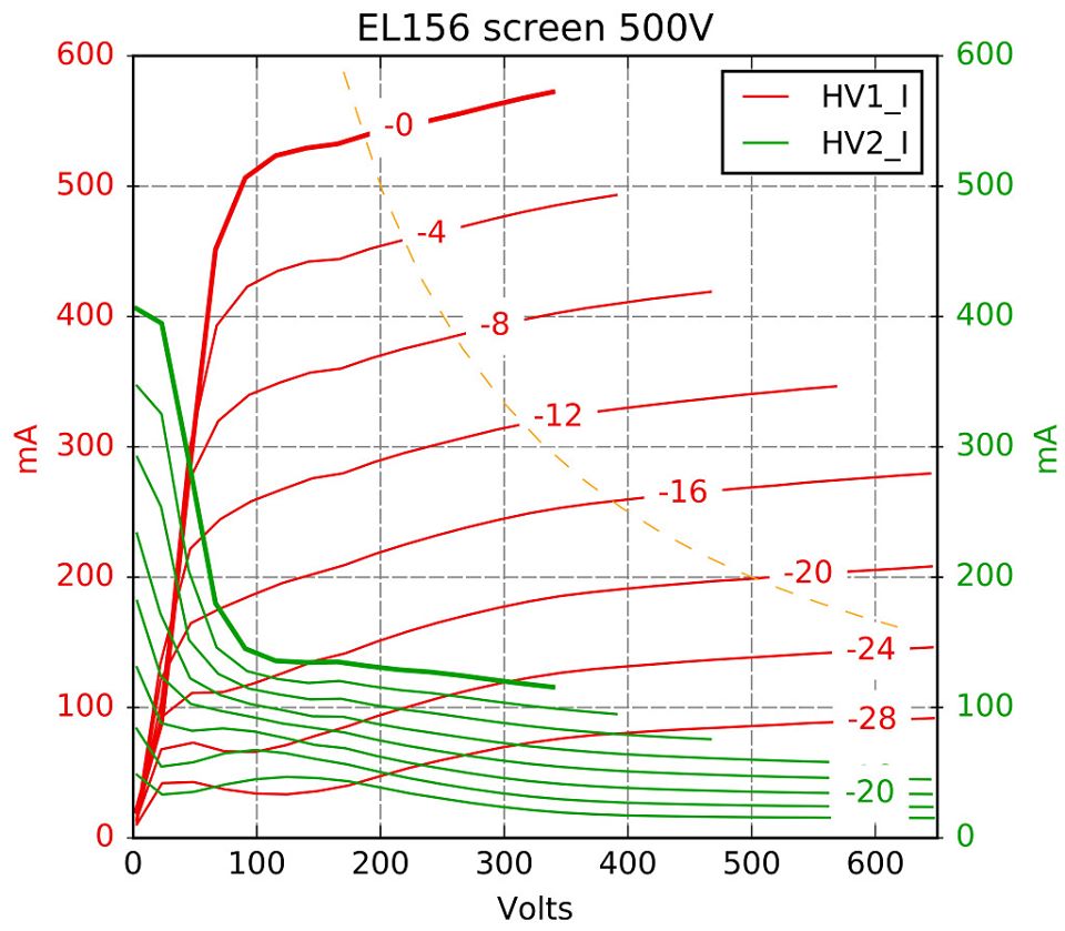
Traces of a Telefunken EL156 under pentode configuration with a screen voltage of 500V
Side effects of the modification
Loss of 1-bit resolution
The maximum current measurement capability of etracer is set to 300mA (Actually about 320mA) . With a 14bit ADC and a PGA of 2x the resolution is 320/2/16384≈10uA. Averaging technique is used in the software to effectively enhance the resolution. Theoretically for an AWGN (additive wide Gaussian noise) background noise the ADC resolution can be enhanced by one bit every time the number of averaging samples doubled. In reality the background noise is never AWGN and the enhancement in resolution is quite limited. Although this resolution is more than enough for testing tubes with current readings in the mA range it is very marginal for Heater-Cathode leakage current measurement where a resolution in the uA range is desirable. If we modify the etracer hardware to support a maximum of 600mA we effectively increase the ADC resolution to about 20uA. This might render the H-C test useless.
Increase of noise floor
With two times of current measurement capability the noise floor is effectively raised by a factor of 2.
Loss of voltage accuracy when HV2 current is high
During current measurement cycle the boosting circuit is turned off to minimize the noise and the DUT is solely powered by the 45uF MKP capacitors. It is inevitable that the voltage on the capacitors will drop gradually when it is discharged through the DUT. The higher the current, the bigger the voltage drop. This phenomenon is usually not a problem for HV1 as the voltage on the capacitor is measured and compensated at the end of a current measurement. However, for HV2 the story might be different in some cases. One obvious example is the DUT is connected as a pentode and HV2 is connected to the screen electrode of the DUT. This voltage needs to be kept as constant as possible. When the plate voltage is low it is known that the screen electrode conduct the most of current. The screen current reading and hence the traced curves will have more error in the low plate voltage range(<=25V or so). As the plate voltage increases the screen current drops rapidly and should not affect most of the traced curves.
Modification steps
Hardware mod
In every high voltage circuits there are two resistors need to be changed: the current limiting resistor and the reference resistor for current measurement. Both resistors need to be halved in value. Below is a simplified circuit for HV1. The current limiting resistor is R48 and the current measurement resistor is R40. There are two easy ways to modify the etracer PCB. One is soldering a resistor of the exact value (8.2 ohms and 15 ohms) in parallel to the existing resistors on the back of PCB. The other is replacing the resistors on the PCB half values (4.1 ohms and 7.5 ohms). The current sensing resistor of 7.5 ohms needs to be exact. The current limiting resistor can be a value between 3.9 ohms to 4.3 ohms as it might not be easy to find an exact value of 4.1 ohms.
The figure below is a simplified circuit when the etracer is performing current measurement for HV1. The discharge path of the high voltage capacitor is marked in red.
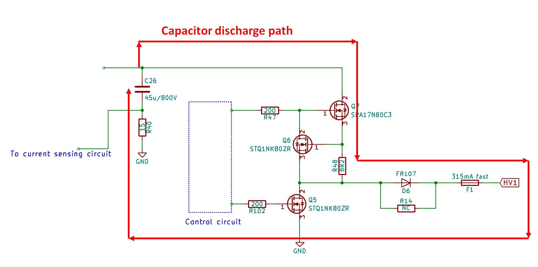
Capacitor discharge path during the current measurement cycle
The corresponding resistors for the HV2 path are R88(15 ohms) and R96(8.2 ohms). The locations of these resistors are marked in red in the picture below.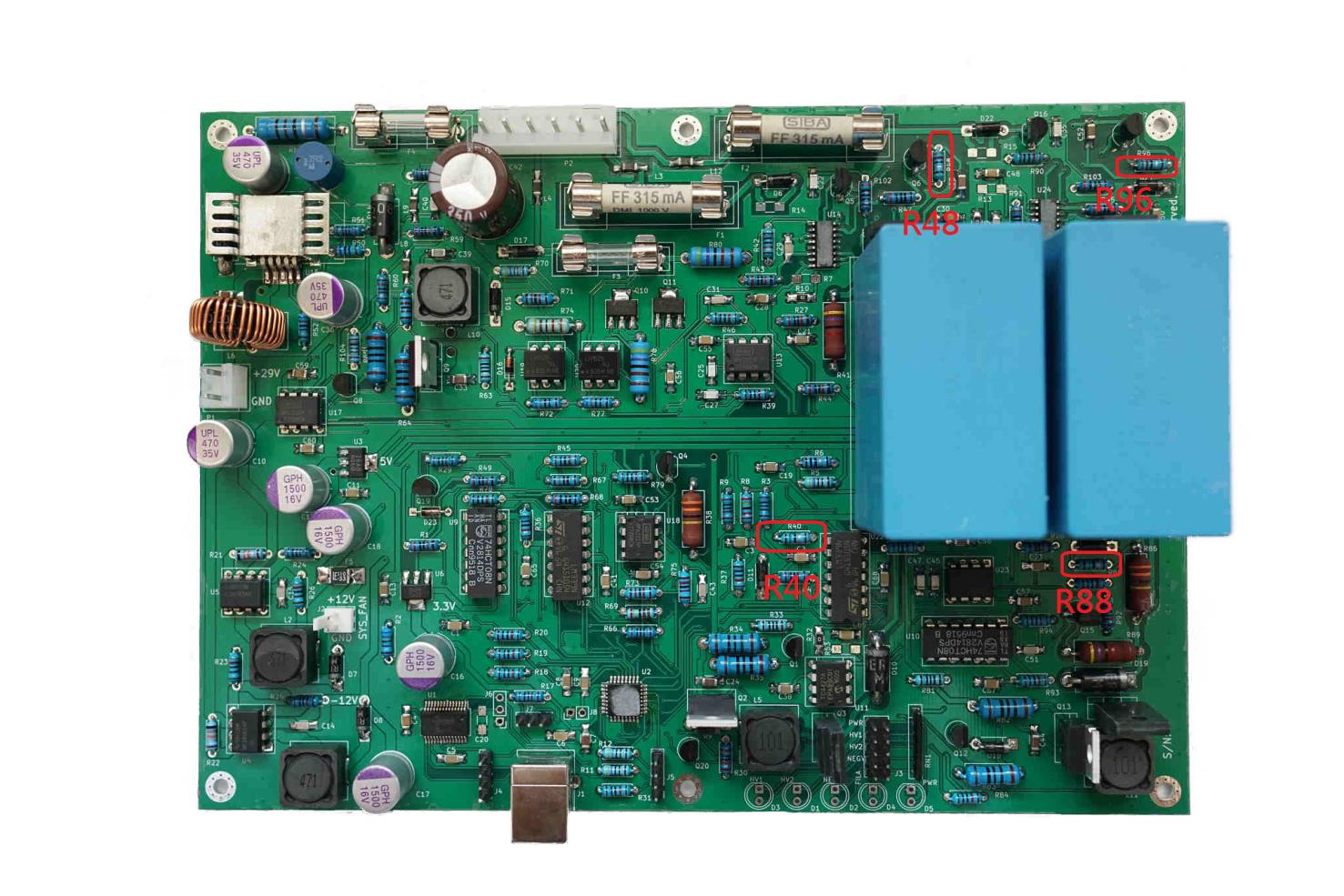
Positions of the 4 resistors to be modified
If the first method (parallel connection mod) is adopted it is very important to make sure a clearance of at least 1mm between the bodies of the soldered components R48 and R96 to the PCB as these components will have a potential as high as the HV output during the current measuring cycle. Below figure illustrate the parallel mod for R40 in the HV1 path.

Parallel mod for R40
Software configuration
Support of 2x current mode is only implemented in the experimental (alpha) version of etracer software starting from software version 2.1.20 alpha. There are two places needs to be configured: The series resistances in the HV circuits and the check box of the 2x operation. We need to subtract the total amount of resistance we reduced with the modification (4.1+7.5=11.6) from the default value of 25 ohms. We will set this value to 13 as thes fields only takes integer values.
The 2x current checkbox is added to the software since version 2.1.16 alpha. Check this box to enable the 2x current code. Please refer to the figure below for the locations of the fields that need to be changed in the configuration window.
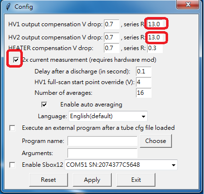
Fields marked in red needs to be set properly in the configuration window
Note: When the status of the 2x current measurement checkbox is changed the software needs to be restarted to operate properly. A reminder message window will pop up when the Apply button is pressed.
New with software version 2.1.23alpha and later
When the software is launched a "2xcurrent" label in red will be displayed in the etracer logo window indicating the software is running under the 2xcurrent mode.
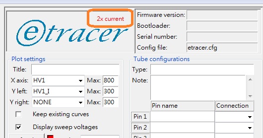
A label in the logo window indicating the 2xcurrent mode is activated
Current calibration
After the 2x modification a full current calibration is required. For a quick verification at least the DC offset calibration is required. It is observed that the curves for DC offset calibration are slightly sloped with the 2x modification. The reason is unknown. Please refer to the below figure for an example of offset current after calibration.
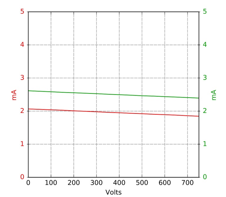
Slightly sloped offset current calibration curves
Footnote
The 2X current mode is not an "upgrade" to etracer. It is only a modification to etracer so that etracer can accommodate up to 600mA. The loss in measurement accuracy is negligible for curves tracing but it will affect the performance of heater-cathode leakage test. Since the heater-cathode leakage is only an experimental feature the modification can be safely done without losing of performance for most etracer users.
We offer a free modification service for all etracer users. The users will need to pay for the round-trip shipping fee.
Please refer to the following video clip for more information on the 2x current mod: