Introduction
When designing a vacuum tube tester there are many factors to consider: the maximum test voltage, the maximum plate current, the range of the negative supply for the grid and the voltage/current rating for the heater to name a few. There are always trade-offs between cost and performance. Here we focus on the high voltage aspect. For an operating voltage as high as 800V DC in etracer the components need to be carefully selected to guarantee a maintenance -free operation for a very long period of time. And like an old saying “Quality doesn’t come cheap” components that are designed for higher voltage applications tend to be bulkier and pricier compared to their lower-voltage counterparts. It is found that several tube testers products and kits in the market have poor components selections. They are attractive at first glance because of the cheaper price tag but they might not last long and they might cause severe damage to the device or incur safety issues if something went wrong.
Semiconductor components consideration
Thanks to the development of modern electrical vehicles there are many transistors and ICs that are designed for a high voltage DC operation. This makes it possible to shrink the size of the design considerably. In the HV MOSFET category the voltage rating for NMOS transistors can be roughly categorized in the following voltage range: 800V, 1200V, 1500V. 800V is a sweet spot because there exist power MOSFETs with a very low drain-to-source resistance,Rds (<50m Ohms) in a TO-220 package and MOSFETs that has a reasonably small TO-92 package. And 800V is suffice for testing most common audio tubes.
The following picture depicts the discharge path of HV1 on etracer during a measurement pulse. It can be seen the current start from the positive terminal of C26 (The blue cap) and flow through Q7 (SPA17N80C3), R48 (8.2 ohms), D6( protection diode), F1 (high voltage fuse) and R40 (15 ohms, current sensing) before it returns to the negative terminal of C26. The overall resistance is approximately 25 ohms (8.2+15+ (Rds of Q7) + resistances for traces and other components). Note the internal resistance (Rds) of Q7 is part of this path and a very low Rds is desired.
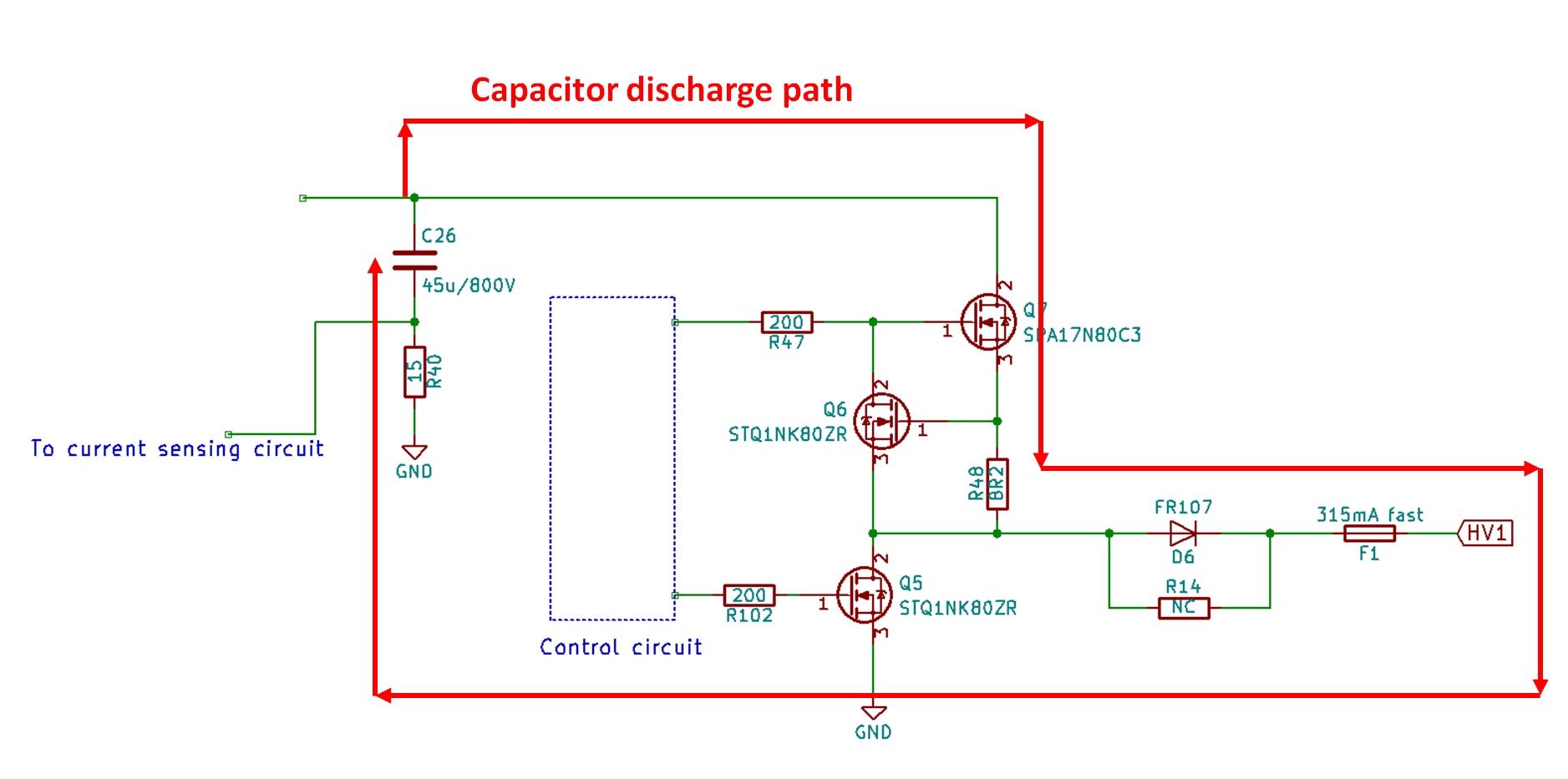
HV1 discharge path during measurement phase
The reason we want a low on-resistance for the NMOS transistor is it's on-resistance is part of the high-voltage supply path of etracer. The on-resistance varies part to part and it also varies with operating temperature. If the resistance is significantly smaller than the sum of all resistive components in the high-voltage discharge path the variation of this on-resistance can be safely ignored. But if the on-resistance is of the same order of the overall resistance it needs to be accurately measured and compensated otherwise measurement accuracy will suffer. Below is an example to illustrate the impact of the on-resistance with an overall resistance of 20 ohms in the HV path:
- Case 1: on-resistance =0.3 Ohms, an increase of 20% takes place due to temperature:
The percentage of overall resistance change=20.36/20.3=100.2% of the original value
- Case 2: on-resistance=8 ohm, an increase of 20% takes place due to temperature:
The percentage of overall resistance change=29.6/28=105.7% of the original value
It can be easily seen that the resistance variation in case 1 can be safely ignored while in case 2 the variation needs to be properly compensated otherwise a 5.7% error exists. Unfortunately compensation for this type of error due to temperature variations is not trivial. Also if the circuit has a smaller overall resistance in order to measure a higher current the error introduced by variation of the NMOS's Rds is also higher. For example, with the 2X current mod the etracer's overall resistance in the HV discharge path is reduced to 13 Ohms and the error for case 1 is 13.36/13.3=100.45% while in case 2 it will rise to (13+9.6)/(13+8)=107.6%!
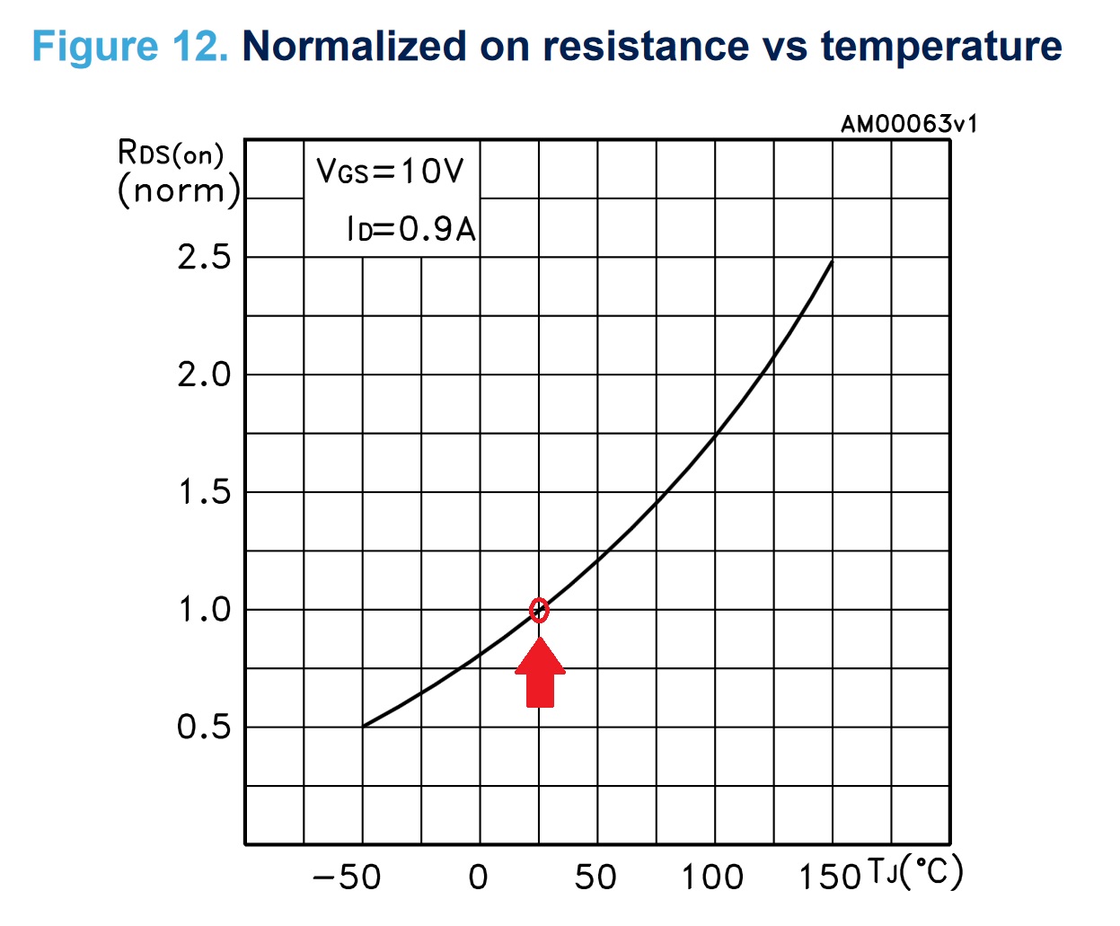
The SPA17N80C3 NMOS transistor used in etracer has a maximum on-resistance of 0.29 ohms at room temperature. Below figure excerpted from the SPN17N80C3 datasheets shows the relationship between the on-resistance and the operating temperature. It can be observed more than 20% variation in Rds would occur with a temperature difference of merely 10 degree Celsius.

On-resistance vs. temperature for SPA17N80C3
If we use transistors such as STD2NK100Z that has the same TO-220 package as SPA17N80C3 with a maximum Vds rating of 1000V the maximum on-resistance is 8.5ohms at room temperature which is 28 times higher than the on-resistance of a SPA17N80C3. Unless we go with a much larger (and much more expensive) package 800V is where we can get a NMOS transistor with a satisfying low on-resistance.
The following figure is excerpted from the datahseet STD2NK100Z. We can observe a similar Rds vs. temperature curve as SPA17N80C3. Note in this figure the curve is normalized at room temperature of 25 degree Celsius (marked in red). We can observe a Rds variation of about 10% when the temperature differences is 12 degree Celsius. Note that 12 degree Celsius can easily be the temperature difference between day and night in some places or the room temperature difference between summer and winter.
On-resistance vs. temperature for STD2NK100Z.
Passive components
The passive components in the HV path of etracer are the big blue rectangular 45uF/800V MKP capacitors for energy storage and some resistors for discharge and voltage-dividing purpose. The two blue MKP box capcitors are pretty much a unique signature of the etracer PCB. The reason we use expensive and bulky MKP capacitors instead of cheap electrolytic capacitors is that MKP capacitor has a far superior characteristic in all aspects: ESR, operating frequency and most importantly the much longer life span. Also it might need to stack two electrolytic capacitors to withstand a voltage higher than 500V which introduce another layer of uncertainty. The MKP capacitors perform well into 200kHz while normal electrolytic capacitors lose it's capacitive characteristic and act more like an inductor at a frequency of merely 20kHz.
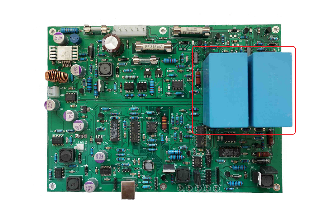
45uF/800V (circled in red) MKP (Metal Polypropylene) capacitors made by Epcos
In the low voltage power supply circuits (+/- 12V DC, 5V, 3.3V and the heater supply) we use only high-quality solid aluminum capacitor that can be found on many high-quality PC motherboards. These capacitors have very low ESRs and very long lifetimes. These solid aluminum capacitors are ordered from GEMCON, an ISO-9000 company in Taiwan.
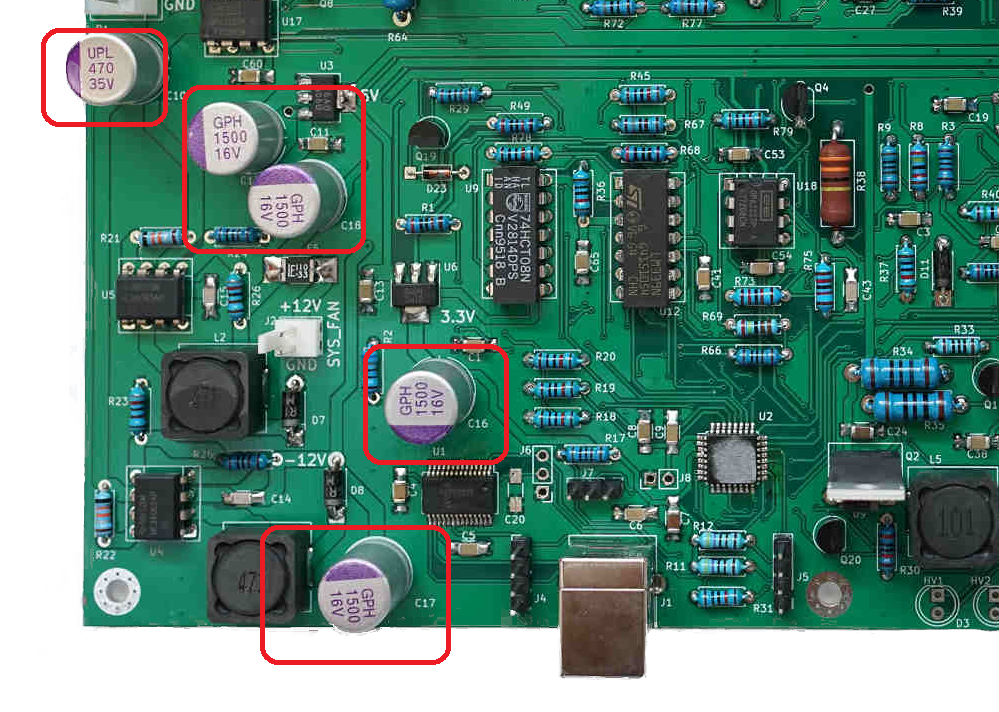
Solid aluminum capacitors (circled in red) on the etracer PCB
As to the resistors it is interesting that not many people are aware of that resistor has a voltage rating besides the power rating. The voltage rating has to do with the internal structure of a resistor. For example a wire-wound resistor is formed by multiple turns of resistive wire and excessive voltage applied on the terminals might cause a short path between the turns. Most resistors are specified up to 300V for insulation which is only less than half of the desired rating of 750V for etracer. The brown through-hole resistors on the etracer PCB are custom ordered from an ISO 9000 company in Taiwan and has an insulation rating of 1500V.
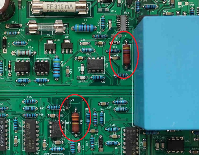
Custom ordered resistors (circled in red) with a voltage rating of 1500V
Fuse, connectors and wires
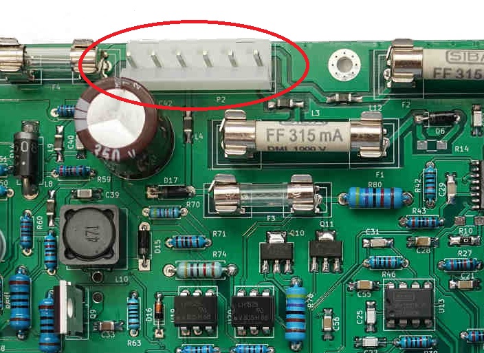
Similar to resistors, fuses have a voltage rating indicating the maximum operating voltage allowed. It might be weird at the first look because a fuse is often considered a conductor with some resistance. However, when a fuse start to melt the voltage across the two terminals might increase significantly and it might cause safety issue (eg. explosion of the glass evenlope) if the fuse is not designed to accommodate this voltage. Common fuses are usually rated below 250VAC maximum because they are commonly used in protecting the AC mains or used low voltage applications. 250VAC rated fuses can be found in a small 5mmx20mm glass form.
For higher voltage protection special fuses are needed. High voltage fuses are more expensive and bulkier. For example, the SIBA 800V/350mA super-fast fuses found on the etracer PCB are 6.3mmx32mm in dimension and are retailed at about USD$8 per piece.

Fuses (circled in red) rated at 1000V used in etracer
The connectors also play a critical role in the high-voltage link. Most small connectors with a pin-spacing of 2.00mm to 2.54mm are not designed to withstand voltages above 250V. Besides pin-spacing the dielectric strength of the connectors also need to meet the voltage criteria. The 5197 series connectors made by Molex used in the etracer PCB have a withstanding voltage rating of 1500VAC/minute and will work reliably at 800VDC under pulse-mode.
Molex 5197 series connector (circled in red)
The 18AWG Teflon insulated wires included in the Model-01 chassis kit are ordered from an ISO 9000 company in Taiwan. These wires meet UL10362 specification and are rated at 600VAC (ie. 840VDC) with a very wide temperature range of -80 to 250 degree Celsius.
Conclusion
For a circuit that works at high voltage it is imperative to select the components carefully. Unfortunately this process can not be easily seen by the end users. And it is directly related to the cost of the product. The components used by etracer were carefully selected at design time to ensure a maintenance-free operation for decades and eliminates possible frustrations and hazards.